Part Two of Two
Recap of Part One: A drunk driver went off the roadway at a high speed striking the guide rail in the median with the driver’s side of the car. The car slid along the guide rail until it reached a point where the guide rail was cracked as the result of a prior accident. The guide rail had not been replaced after the prior accident and thus failed in the second accident.
A litigation graphics package was designed to orient viewers to the accident scene, and integrate the visual evidence to provide the context for understanding this evidence. Part One concludes by presenting the visual evidence that both accidents happened in the same location on different sides of the guide rail.
Part Two covers the remaining objectives of the litigation graphics:
Show the relationship between the September and February accidents.
Present material science expert analysis of the fractured guide rail that demonstrates the direction and propagation of the crack in the first accident.
The September 2012 accident
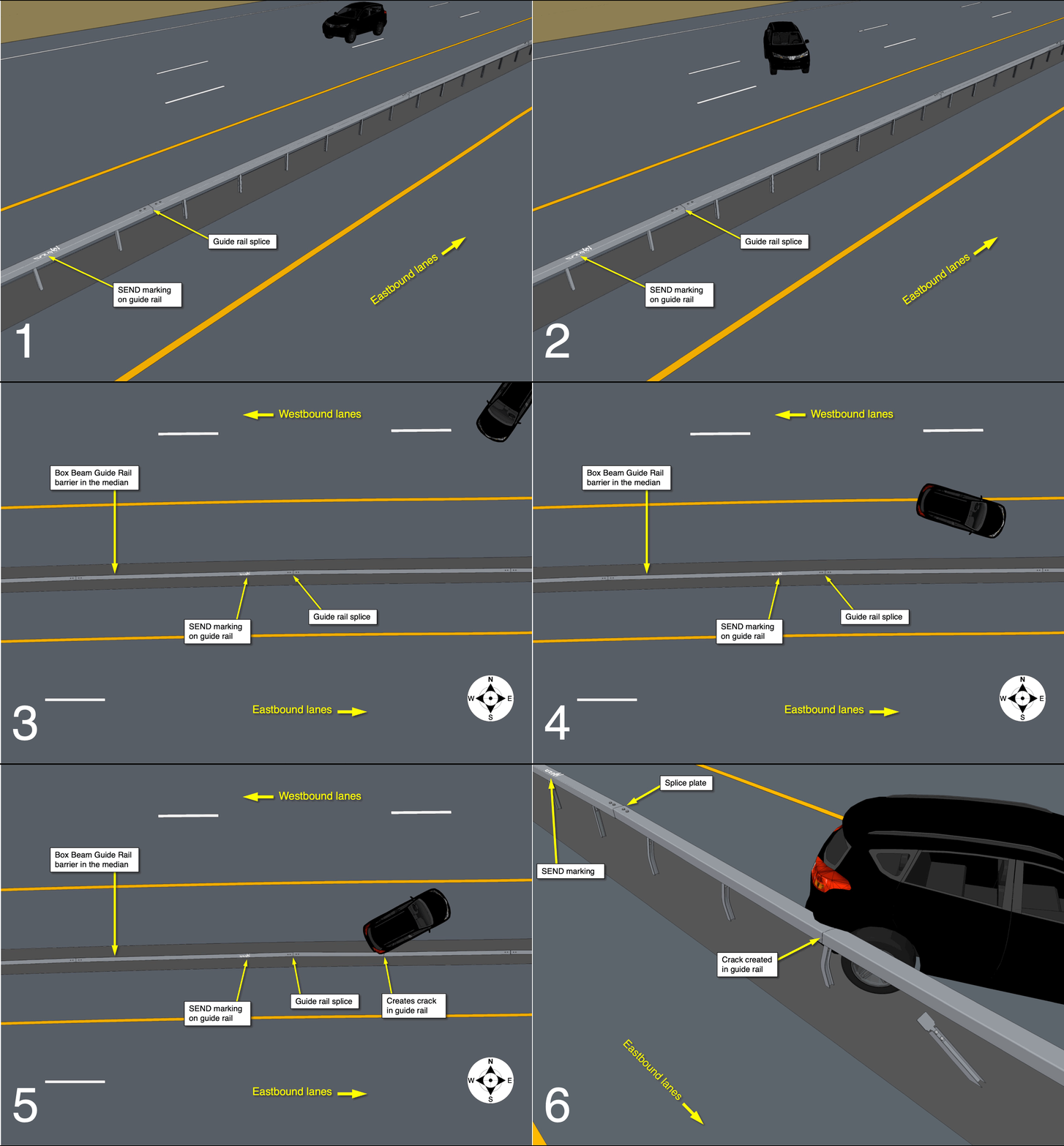
The September accident sequence was illustrated with three different viewpoints in the 3D model as shown below. The path of the vehicle was derived from the State Police report diagram. The resting position of the vehicle was recorded in a witness photo showing the relationship of the vehicle to the guide rail. The last point of view in the September sequence is used as the first view in the February accident sequence.
The February 2013 accident (subject accident of the litigation)
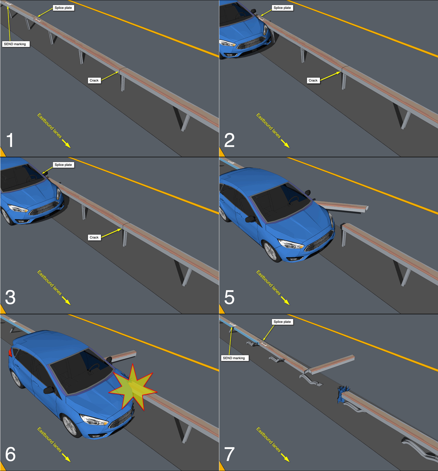
The vehicle struck the guide rail to the West of the September accident location. The vehicle slid along the guide rail until the lateral force of the vehicle caused the guide rail to fail at the crack location. The guide rail section tore away creating a break so the next section impaled the vehicle killing the driver and severely injuring the passengers. The 3D model was used here to illustrate the progression of the vehicle along the guide rail to the point where the guide rail failed at the crack, broke apart, and impaled the vehicle.
September and February accident diagrams combined
Utilizing a top view of the 3D model, both accidents were illustrated in combination. A series of distinct characteristics and markings on the guide rail common to both accidents had been established through a detailed visual analysis of photographs from both accidents. The reconstruction of the two accidents in combination based on the visual evidence in the case not only illustrated the theory of the guide rail failure in the second accident but provided a concise overview of the evidence that proved the two accidents impacted the same section of guide rail.
Materials Scientist Expert Witness testimony illustrated
The subject guide rail is designed to guide vehicles away from potentially hazardous situations and back to the roadway. The rail is a steel tube, rectangular in cross-section, measuring eight inches by six inches. The expert testimony in this case centered around analysis of the fractured surface where the guide rail cracked. The expert’s opinion stated the failure of the guide rail was caused by lateral forces applied to the guide rail by the vehicle approaching the pre-existing crack in the steel tube structure.
The expert analysis of the broken guide rail section concluded the physical characteristics of the fractured surface demonstrated the crack was a result of the September accident. The expert identified features of the fractured surface that indicated a directional pattern of failure. The direction of the crack progression was determined to have initiated at the post slot in the bottom of the guide rail, proceeded up the westbound side and across the top surface to the eastbound side. A second, small branching crack was identified at this point that also indicated the crack was caused by an impact from the westbound side.
The strategy used to present this concept was first to relate the photographic evidence of the failed guide rail to the context of the accident scene. The broken end of the guide rail was rendered in the 3D model from a viewpoint similar to the expert’s evidence inspection photo. This photo was then used as a reference for presenting high resolution images of the fracture surface features used in the material analysis to determine the direction of crack propagation.
Conclusion
Litigation graphics presentations are designed to illustrate the story the attorney tells in court in a clear, compelling, and accurate manner. The natural progression of storytelling is to first orient the viewer to the subject incident, then focus in on specifics all the while incorporating and giving context to case evidence so the viewer understands the significance of the evidence to the overall story. When technical elements are critical to the understanding of the evidence it is important as finer details are revealed to maintain a logical progression through the story so the technical evidence is understood clearly. In this case, the natural progression of developing the graphic presentation resulted in conclusive evidence that proved the theory of the failure in the accident.
-
August 2023
- Aug 2, 2023 Introducing: The Expert Witness, a New Novel Aug 2, 2023
-
June 2023
- Jun 9, 2023 Finite Element Analysis Confirms Thermal Behavior of a Masonry Column Jun 9, 2023
-
April 2023
- Apr 27, 2023 3D Roof Fire Reconstruction Apr 27, 2023
-
March 2023
- Mar 24, 2023 Graphic Diagrams Demonstrate Biomechanics Mar 24, 2023
-
February 2023
- Feb 23, 2023 3D Modeling Combined with Weather Data Analysis Illustrates Expert’s Opinion Feb 23, 2023
-
January 2023
- Jan 25, 2023 Scene Documentation Reveals Evidence of Internal Building Failure Jan 25, 2023
-
August 2022
- Aug 25, 2022 Graphic Reconstruction Proves Theory in a Motor Vehicle Accident - Part Two Aug 25, 2022
-
July 2022
- Jul 20, 2022 Graphic Reconstruction Proves Theory in a Motor Vehicle Accident Jul 20, 2022
-
June 2022
- Jun 15, 2022 Litigation Graphics Strategies Explain a Complicated Loss Jun 15, 2022
-
May 2022
- May 17, 2022 Do I Need a Demonstrative Evidence Expert to Illustrate My Testimony? May 17, 2022
-
April 2022
- Apr 14, 2022 Arc Furnace Failure Illustrated Apr 14, 2022
-
March 2022
- Mar 23, 2022 Fire Litigation Exhibit Options Mar 23, 2022
-
February 2022
- Feb 16, 2022 Gas Explosion Investigation Enhanced by 3D Reconstruction of Building and HVAC System Feb 16, 2022
-
January 2022
- Jan 18, 2022 Scene Reconstruction Illustrates Non-Compliant Furnace Installation that Caused a Fire Jan 18, 2022
- Jan 5, 2022 3D Scene Reconstruction of Cold Storage Facility Serves as a Critical Tool in Fire Investigation Jan 5, 2022


