
Some accidents are not complex in terms of setting or biomechanics. In these cases, a few slides may suffice to illustrate whether the accident victim’s testimony is accurate or not. The example below is from a case where the plaintiff was measuring a window on the side of a building. The fence post next to the building broke and he fell over a retaining wall to the ground eight feet below. The plaintiff testified he had his left hand wrapped around the top rail of the fence when it broke, “pulling him over the wall”. Simple illustrations showing the forces necessary for the accident to happen in this manner demonstrate how unlikely it was for the accident to have occurred in this manner.
Side view of the plaintiff in the position he described
Measurement and Modeling
Accident scene documentation and scale reconstruction are critical to the understanding of an accident like this. All significant aspects of the site were measured. A 3D computer model was created for the purpose of placing a scale figure into the scene. Measurements of the wall and fence show he has to be at least 14 inches away from the edge of the wall. Images were created from the model to illustrate the plaintiff’s position and the forces that would be required to cause him to fall over the wall.

3D model of accident scene created from site measurements
Testimony: Pre-Accident Position
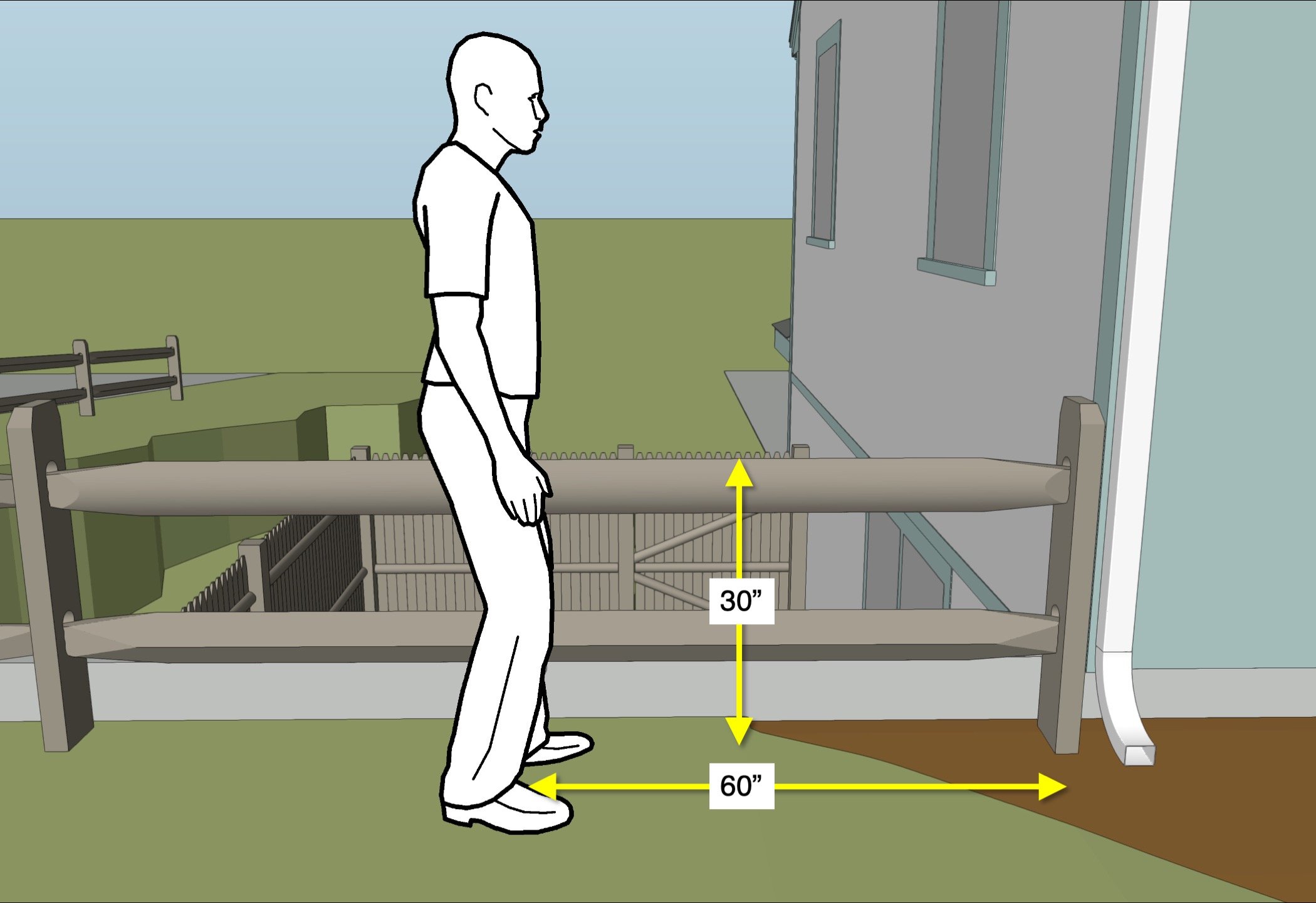
The illustrations were created to depict the plaintiff’s position near the retaining wall based on his testimony. The plaintiff described his position:
He was standing on the street side of the fence with his left hand on the top rail. His right hand was by his side.
He was facing the house with his toes pointed toward the house.
He was five feet from the house. The fence rail is ten feet between posts, so he was halfway between the post that failed and the next one away from the house.
His left hand was grasping the rail and was nearly all the way around the top rail.
His left hip was close to the rail and may have been touching the fence.
He was 5’11” and weighed 175 lbs.

View of the plaintiff in the position next to the fence he described.
Testimony: Accident Description
His testimony was as follows:
He felt the rail move and he grabbed it.
His shoulder was not over the fence.
He was standing straight up.
His feet went into the air, he “flipped in the air, head over heels as if I had been pulled” and fell over the wall.
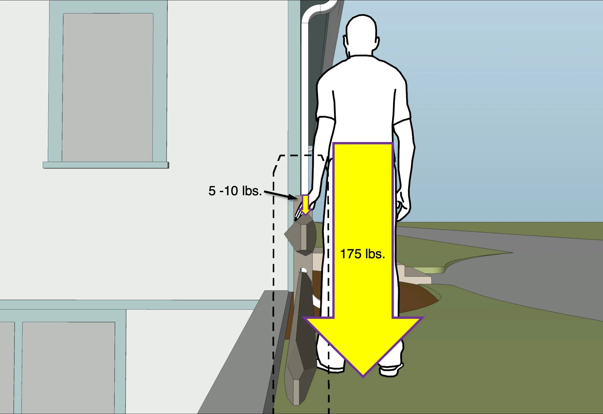
Analysis of the forces involved: 5 - 10 pounds on the fence rail, 175 pounds on the ground.
Expert Analysis and Calculations
Holding the rail with his left hand would be less than 10 pounds of force. Measurements of the rail cross-section show it would be improbable for his hand to be wrapped around the rail. His weight downward is 175 lbs. It would take about 60 pounds of force to push his center of gravity 24 inches toward his left side sending him over the wall. The force flipping his feet in the air would be about 90 pounds acting on his feet causing him to rotate around his center of gravity. The story is not correct. He must lean against the fence with 50-100 pounds of sideways force to break the post or, more likely, be on the other side of the fence and pull on the rail, breaking the post, as he tries to stop his fall over the wall.

Conclusion
The graphics are simple yet communicate quite clearly the plaintiff’s testimony is incorrect. Basic laws of physics were illustrated in the context of an accurately scaled model of the accident scene.
-
August 2023
- Aug 2, 2023 Introducing: The Expert Witness, a New Novel Aug 2, 2023
-
June 2023
- Jun 9, 2023 Finite Element Analysis Confirms Thermal Behavior of a Masonry Column Jun 9, 2023
-
April 2023
- Apr 27, 2023 3D Roof Fire Reconstruction Apr 27, 2023
-
March 2023
- Mar 24, 2023 Graphic Diagrams Demonstrate Biomechanics Mar 24, 2023
-
February 2023
- Feb 23, 2023 3D Modeling Combined with Weather Data Analysis Illustrates Expert’s Opinion Feb 23, 2023
-
January 2023
- Jan 25, 2023 Scene Documentation Reveals Evidence of Internal Building Failure Jan 25, 2023
-
August 2022
- Aug 25, 2022 Graphic Reconstruction Proves Theory in a Motor Vehicle Accident - Part Two Aug 25, 2022
-
July 2022
- Jul 20, 2022 Graphic Reconstruction Proves Theory in a Motor Vehicle Accident Jul 20, 2022
-
June 2022
- Jun 15, 2022 Litigation Graphics Strategies Explain a Complicated Loss Jun 15, 2022
-
May 2022
- May 17, 2022 Do I Need a Demonstrative Evidence Expert to Illustrate My Testimony? May 17, 2022
-
April 2022
- Apr 14, 2022 Arc Furnace Failure Illustrated Apr 14, 2022
-
March 2022
- Mar 23, 2022 Fire Litigation Exhibit Options Mar 23, 2022
-
February 2022
- Feb 16, 2022 Gas Explosion Investigation Enhanced by 3D Reconstruction of Building and HVAC System Feb 16, 2022
-
January 2022
- Jan 18, 2022 Scene Reconstruction Illustrates Non-Compliant Furnace Installation that Caused a Fire Jan 18, 2022
- Jan 5, 2022 3D Scene Reconstruction of Cold Storage Facility Serves as a Critical Tool in Fire Investigation Jan 5, 2022