

Post-explosion photo of residential duplex
A gas explosion and fire destroyed a residential duplex late one January night, injuring two occupants. 60 feet away from the building, a gas leak was discovered in a six-inch main under the street. The gas service for the duplex was connected to a separate, twelve-inch main. It was not clear there was any connection between the leak and the explosion. Subsequently, scene investigators discovered a large crack in the foundation on the origin side of the duplex.

Pre-explosion view of site
Drake Exhibits was retained to document all aspects of the building. The building structure, mechanical & electrical systems, gas piping, and gas appliances were documented with measurements, photographs, and video. A thorough forensic investigation was conducted by a multidisciplinary team of experts to establish the factors that contributed to the explosion.

3D computer model of the overall structure
Jeff Drake created a 3D reconstruction of the building including a detailed layout of the basement, gas piping, gas boiler, and ductwork. The model was used as a guide during discussions and meetings to help the experts develop a common understanding of the building. Details were added to the 3D reconstruction as the investigation proceeded. Additional inspections were scheduled to obtain more specific information about the building.

Basic construction details of basement illustrated
The force of the explosion blew all the doors and windows out of the right side of the duplex. The exterior walls on the first and second floors were displaced by several inches. A detailed examination of the structure documented the movement of the walls and the failed nail connections. It was unclear how gas leaking into the basement would cause this damage. As part of the forensic investigation, engineers calculated the force required to create the level of damage recorded. This data was a key variable used in determining the volume of gas in the building.
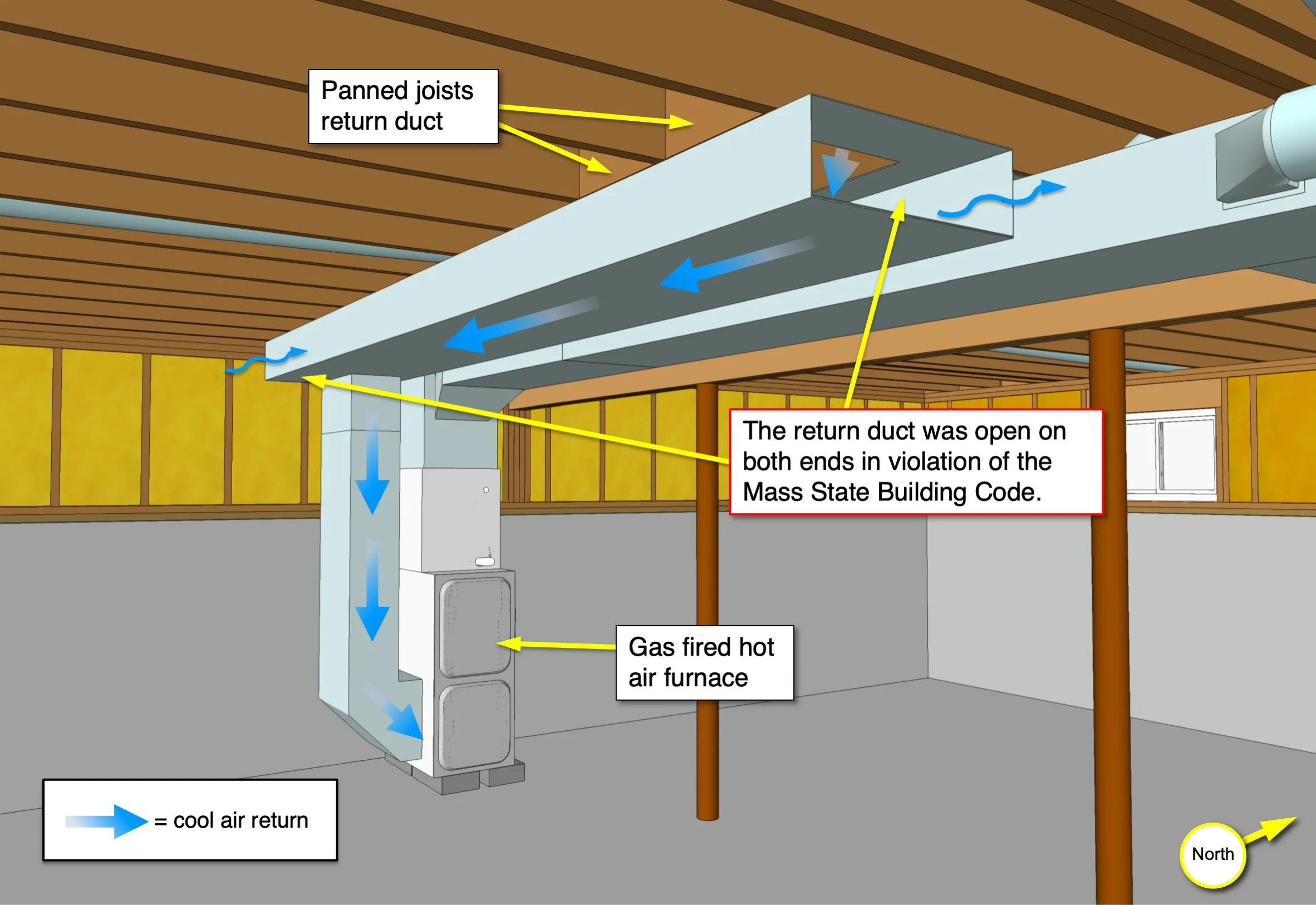
Non-compliant HVAC installation
During one inspection, it was discovered that the main section of return air ductwork was missing end caps, leaving the return air system open to the basement atmosphere. Jeff Drake documented and modeled all the ductwork in the building for use by fire protection engineers to model the building’s airflow. Geotechnical engineers determined the ground conditions between the leak and the basement would allow for gas dispersion through the soil. A test was conducted to measure airflow through the crack into the basement.

Detailed cutaway views of the structure and HVAC system used to illustrate the return air flow and influx of gas/air into the basement through the crack in the foundation
The HVAC system also had an undersized return grill, which in combination with the open ductwork created a negative pressure (a vacuum) in the basement, drawing outdoor gases (air and migrating natural gas) into the basement. These conditions explained how gas in the ground outside was pulled into the basement and circulated by the hot air system through the house until it reached critical concentration and found an ignition source. The 3D reconstruction was instrumental in cementing the investigative team’s understanding of the building and mechanical systems. The 3D reconstruction also served as the basis for a series of graphics used at mediation.
Ask a question . . .
-
August 2023
- Aug 2, 2023 Introducing: The Expert Witness, a New Novel Aug 2, 2023
-
June 2023
- Jun 9, 2023 Finite Element Analysis Confirms Thermal Behavior of a Masonry Column Jun 9, 2023
-
April 2023
- Apr 27, 2023 3D Roof Fire Reconstruction Apr 27, 2023
-
March 2023
- Mar 24, 2023 Graphic Diagrams Demonstrate Biomechanics Mar 24, 2023
-
February 2023
- Feb 23, 2023 3D Modeling Combined with Weather Data Analysis Illustrates Expert’s Opinion Feb 23, 2023
-
January 2023
- Jan 25, 2023 Scene Documentation Reveals Evidence of Internal Building Failure Jan 25, 2023
-
August 2022
- Aug 25, 2022 Graphic Reconstruction Proves Theory in a Motor Vehicle Accident - Part Two Aug 25, 2022
-
July 2022
- Jul 20, 2022 Graphic Reconstruction Proves Theory in a Motor Vehicle Accident Jul 20, 2022
-
June 2022
- Jun 15, 2022 Litigation Graphics Strategies Explain a Complicated Loss Jun 15, 2022
-
May 2022
- May 17, 2022 Do I Need a Demonstrative Evidence Expert to Illustrate My Testimony? May 17, 2022
-
April 2022
- Apr 14, 2022 Arc Furnace Failure Illustrated Apr 14, 2022
-
March 2022
- Mar 23, 2022 Fire Litigation Exhibit Options Mar 23, 2022
-
February 2022
- Feb 16, 2022 Gas Explosion Investigation Enhanced by 3D Reconstruction of Building and HVAC System Feb 16, 2022
-
January 2022
- Jan 18, 2022 Scene Reconstruction Illustrates Non-Compliant Furnace Installation that Caused a Fire Jan 18, 2022
- Jan 5, 2022 3D Scene Reconstruction of Cold Storage Facility Serves as a Critical Tool in Fire Investigation Jan 5, 2022